Saturday 13 August 2011

Tesla coil; resonance demonstration.

Today i ve nothing new project to post except to just wanna explain my recent demonstration of resonance and wireless energy transfer using mini Tesla coil i ve built recently.

Resonance is the very fundamental concept that enables the functions of most current ubiquitous wireless devices. Radio receiver, handset, radar,satellite and televisions are all dependent on this principle.

Resonance occurs when the frequency of the energy supplied to a system is the same as the natural frequency of the system. At resonance, the system will receive most energy from the energy source, and tend to damage itself, unless controlled.

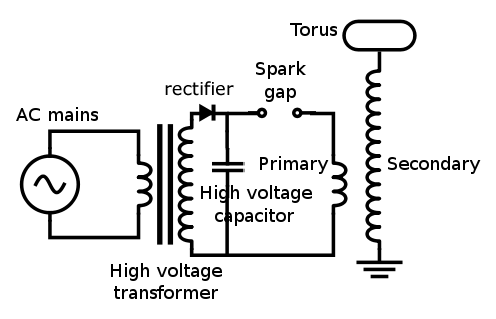
In Tesla coil, like no other conventional transformers, the secondary coil resonates with the primary coil. Hence, most of the energy supplied by the primary coil will be intercepted by the secondary coil and this in turn increases efficiency. To achieve this, of course (by the definition of resonance) the natural frequency of the tank circuit formed by the capacitor and the primary must be the same with the tank circuit formed by the air-earth 'capacitor' and the secondary. Since the secondary coil tends to damage itself with excessive energy being transferred into it, therefore a spark gap is made at the primary coil to release the excess energy.

Since resonance occurs at the same frequency of energy source and receiving system, i wondered whether the energy received by the secondary coil can be transferred further to a similar system with same or almost same natural frequency. Due to this, i constructed a third coil , which is having same diameter, length, wire diameter in order to make its natural frequency as close as possible to that of the secondary coil. The following diagram shows the secondary coil and the third coil.

Both coils, secondary and third coils.

Current setup. Its the same i ve been using before. The 275ml bottle wrapped in aluminium foil is my homemade capacitor. I chose this one cuz it gives longest spark on the secondary ie it enables the primary ( the yellow wire) to resonate with the secondary.

The system, without the third coil. A strand of corona was pulled by using screwdriver. Its about 1.5cm length.

When putting the third coil in the vicinity of the secondary coil, it resonates and due to this, a 0.7cm can be observed between the screwdriver and the breakout point. How do i prove that it really resonates and not receiving energy from the yellow wire ( the primary coil)? I removed the secondary winding away, and then tried powering the circuit again. And no spark was observed at the third coil. This proves that it really resonates with the secondary coil.

How the resonance is applied in telecommunication? Well, i guess u can contemplate over the experiment. The secondary is the transmitter of the energy while the third coil is your 'handset', television, radio receiver and any type of wireless devices. The differences between resonance observed in my demonstration and the resonance in real application in wireless devices are that the power is transferred at larger distance and higher band of frequencies, and the power is not only bringing itself, it also brings signals ( it is modulated )that will be translated and amplified into perceivable video and audio signals.


Monday 8 August 2011

Tesla coil; first attempt.

Tesla coil is a type of resonant transformer, where the voltage output from the secondary turn is not dependent on the turns ratio between primary and secondary turns, but dependent on the square root of the ratio between primary inductance and secondary inductance.

Here is my first attempt on building a mini Tesla coil. The secondary coil (where the sparks will be observed) is a 500-turn winding, wound around a kitchen naptkin's cardboard roll of 5cm outer diameter and of 20cm length. The primary coil is 8-turn winding, wound around a big glue tape roller of about 9cm outer diameter. I drive this coil using ZVS power oscillator (see schematic here) but using different type of capacitor (1uF, non polar). Like no other configuration of the ZVS, this new configuration of ZVS i ve been using rendered the MOSFETs very hot after 1 minute running time, forcing me to put heatsinks on each MOSFET.

Running on 12V, 3.16A power supply fed into the ZVS circuit. I am still researching on how to enlarge the spark and make them blue since the purple spark is not a spark, its a corona due to presence of water vapor around the carrying conductor.

I dont know why the camera suddenly perceived the spark as blue although it was purple.

In the dark.

I m using spark gap, so this tesla coil can be regarded as SGTC (spark gap tesla coil).

The capacitor i ve been using is a single homemade leyden jar, made from 275ml juice bottle, with brine in it and aluminium on the outer part as plates.

Here is the schematic of the tesla coil from the high voltage output. The diode is already in the flyback transformer that receives oscilated current from the ZVS circuit.

I m still improving the design to get larger spark and less hot transistors. See ya later.


Thursday 4 August 2011

Zero voltage switching (ZVS) technique.

Though the 555 driver i ve been using is quite good in running the flyback, however the MOSFETs were easily heated up . I ve broken about 3-4 MOSFET since i ve been using it. Therefore, when i was searching for a more robust flyback driver in order to use it as my tesla coil power supply afterwards, i realized that zero voltage switching (ZVS) flyback driver can give high voltage without heating the MOSFET too much ( sometimes even none!). Hence, i turned to ZVS from that instance.

The most popular ZVS flyback driver nowadays amongst hobbyists is that designed by Vladimiro Mazilli. This driver is called zero voltage switching driver cuz it switches current exactly when the voltage across the MOSFET equals zero, and give a pure sine wave output, hence behaving like an DC-AC converter or 'inverter'. Due to its ability to convert the input DC into sine wave rather than sawtooth signal (from 555 driver circuit), hence the noise or the transformer's hum can be reduced or sometimes, entirely eliminated at all.

I ve been testing the ZVS driver with all electronic components i ve got so far ( since i dont wanna buy too much to reduce cost, i m short of money right now), and yesterday i finally found the most optimal configuration or variant of the circuit, where no more mosfet, diode and zener diode are broken ( honestly, i ve broke several zener diodes, some mosfets and also common rectifier diodes in the process).

The spark generated from the transformer is quite solid and smooth, no hum from the transformer's core, and the mosfet and all of the components on the circuit are not even getting warm at all. The only disadvantage from ZVS driver i recognised so far is that it generates less voltage than its 555 counterpart ( hence smaller spark), but i can increase it with Villard cascade since it is a sine wave alternating current anyway. Furthermore, my pack of 1000 diodes had arrived yesterday from Hong Kong since bought it last week from ebay. So maybe i can use these diodes to create Villard cascade and some juice glass bottles for the high voltage capacitors.

Here is the schematic of the ZVS driver circuit, with the components are my own selection and the original circuit can be seen here.


About the circuit ( with reference to the schematic);
Speaking from experiences, I think the most critical parts of this circuit are the diodes, and the primary inductor. Prior to using 1N4007 diodes, i used 1N4148 and broke about 4 to 5 of them, maybe due to high current ( the high current split them into two!). Therefore, if u wanna choose suitable type of diodes, make sure their ratings can stand the current u wanna use. I also tested salvaged diodes from old TV, 1N5401 ( diodes for 3A current) and it works as well.

For the inductor, i just followed the recommended value by Mazilli which is between 40 to 200 microHenries. I chose 167microHenries, by winding breadboard wire with 35 turns around a ferrite core of 1cm diameter and 6cm length. Too low an inductance ( for example, lower than the recommended range) will cause overheating, while too high ( higher than the recommended range) will cause less voltage on the output.

Other parts are not quite critical, you may test by yourself, broken mosfets and diodes are common and something u always have to bear in mind when testing a power circuit like this.

Here are photos taken:
Overall setup

Flyback transformer. Notice 6 turns on each primary winding, both primary windings are connected to each other with a center tap.

Flyback transformer and the circuit ready for running

Power supply and inductor. Yellow thing is the inductor while the black wire is the laptop power supply that gives 9V, 3.16A power.